This block is a sound detector. Using data wires, it can send out the current sound value and a logic signal (true/false) based on whether the current sound value falls above or below a trigger point.
A trigger point is the specific value in a range of numbers where a change in condition occurs. For example, you might program your robot to move forward only when the sound level rises above 60%. The trigger point would be 60.
Specify the trigger point by using the slider or by typing a value into the input box. To specify the range (above or below the trigger point) that will generate the "true" signal, use the radio buttons or the pull-down menu. The "true" portion of the range will be in color; the "false" portion will be gray.
The default setting for the sound sensor block is for sound levels above 50% to generate a "true" signal. The radio button to the right of the range is selected and the slider is set at 50. To switch the "true" portions of the range (setting values below 50% as "true"), you would select the left radio button.
The feedback box in the configuration panel shows the current sound value. (To receive feedback, make sure that the sensor is connected to the chosen port and that communication has been established with the NXT.)
You must drag at least one output data wire from this block’s data hub to another block for any information to be sent. (See the Data Hub section for more information.)
![]() Tip: How do I set the Trigger Point for the Sound Sensor?
Tip: How do I set the Trigger Point for the Sound Sensor?
If you want a loud clapping sound to generate the "true" signal, try clapping a few times and watching the sound values displayed in the feedback box. If your clapping generates sound levels of around 80%, you might set the trigger value at 70. That way, only louder sounds above 70% (like your clapping) will generate a "true" signal. Quieter sounds will be ignored.
The trigger point can be set dynamically by an input data wire.
Display Settings

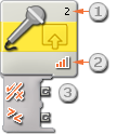
- The number shows which of your NXTs ports is connected to the sound sensor. You can change this number in the configuration panel if you need to.
- This icon indicates at what level the trigger point is set. The more colored bars displayed, the higher the trigger point.
- The block’s data hub will open automatically when the block is attached to a sequence beam. At least one data wire must be dragged from the block’s output plug to another block’s data hub. (See the Data Hub section below for more information.)
Configuring the Sound Sensor Block

- Choose the port where your sound sensor is plugged in. By default, the block will be set to port 2 for a sound sensor. You can change this selection if you need to.
- Use the slider to set the trigger value or type a value directly into the input box. Select the radio button to the right of the slider if you want the block to be triggered by sound levels higher than the trigger value; select the left radio button to trigger the block with sound levels lower than the trigger value. You can also use the pull-down menu to set the "true" portion of the slider.
- The feedback box displays the current sound reading (0-100%). You can use it to try out different trigger values.
Configuring the Sound Sensor block’s Data Hub
You can control the Sound Sensor block dynamically by connecting data wires (from other blocks’ data hubs) to the Sound Sensor block’s data hub.
Open a block’s data hub by clicking the tab at the lower left edge of the block after it has been placed on the work area.

Data wires carrying input information to a block are connected to the plugs on the left side of its data hub. Data wires carrying output information are connected to the plugs on the right side.

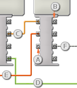
[A] Input plug
[B] Output plug
[C] Number data wire (yellow)
[D] Logic data wire (green)
[E] Text data wire (orange)
[F] Broken data wire (gray)
Passing data from the input plug to the output plug
If an input plug has a corresponding output plug (see A above), the input data will pass through from the input plug to the output plug without being changed. In this case, you can only use the output plug if the input plug is connected to an input data wire; connecting an output data wire to such an output plug without a connected input data wire will cause the output data wire to be "broken" (and colored gray).
Data wires carry specific types of data
Each data wire carries a specific type of data between blocks. For example, if a data wire is dragged from a logic plug on a block’s data hub, it can only be connected to a logic plug on another block’s data hub. The chart below shows what kind of data each plug can accept or send out.
Data wire colors
Data wires are identified with specific colors: wires carrying number data are colored yellow, wires carrying logic data are colored green, and wires carrying text data are colored orange.
"Broken" data wires
If you try to connect a data wire to a plug of the wrong data type, the data wire will be broken (and colored gray). You will not be able to download your program if a data wire is broken.
If you click a broken wire you can read why it is broken in the small help window in the lower right corner of the work area.
Data must be within the possible range of the plug
If an input data wire transmits a value outside the possible range of the plug it is connected to, the block will either ignore the value or change it to a value within its range. For plugs that allow just a few input values (example: just 0, 1, or 2), the plug will ignore the input if a value arrives outside its range.
For plugs that accept larger input ranges (example: 0 – 100), the plug will force any input outside its range to fit. For example, if a Move block’s Power plug receives an input value of 150, the block will change the input value to 100 (i.e., a number within the Power plug’s range).
This chart shows the different characteristics of the plugs on the Sound Sensor block’s data hub:
| Plug | Data Type | Possible Range | What the Values Mean | This Plug is Ignored When... | |
| Port | Number | 1 - 4 | 1 = Port 1, 2 = Port 2, 3 = Port 3, 4 = Port 4 | ||
| Trigger Point | Number | 0 - 100 | Value to compare against | ||
| Greater / Less | Logic | True/False | Logic used in comparison: True = Greater, False = Less |
||
| dBA | Logic | True/False | True = dBA mode False = dB mode |
||
| Yes / No | Logic | True/False | Result of comparison | ||
| Sound Level | Number | 0 - 100 | Scaled value read from sensor | ||
| Raw Value | Number | 0 - 1024 | Raw (unscaled) value read from sensor |